Electric Actuators
Electric Actuators
We are Supplier of Electric Actuators, Electrical Actuator, Electrical Actuator with Starter, Electrical Actuator with Worm Gear Box, Electrical Actuator with Spur Gear Box, Electrical Actuator with Bevel Gear Boxes.
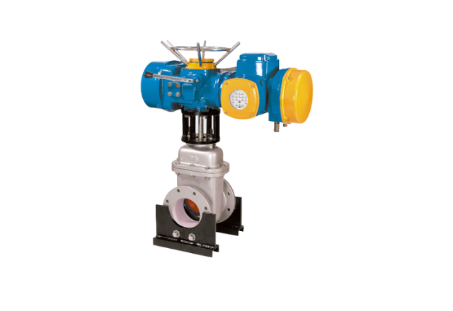
Actuators
with Gear Box
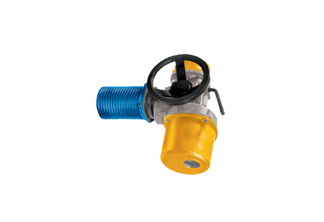
Actuator + Worm Gear Box
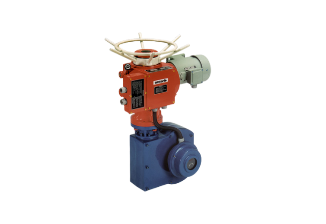
Actuator + Worm Gear Box
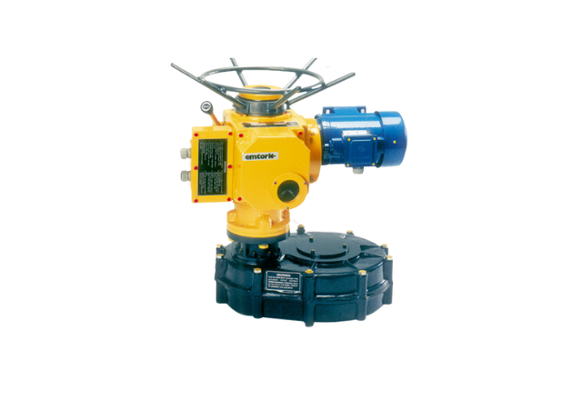
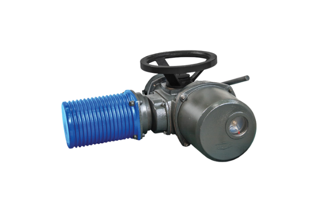
Actuator + Spur Gear Box
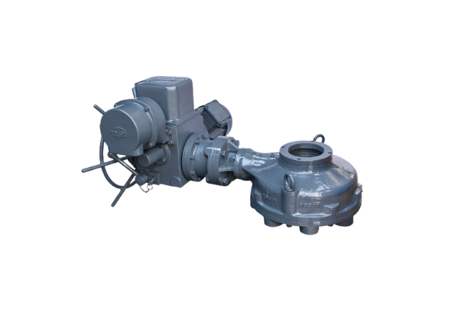
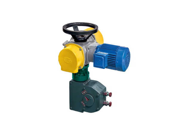
Actuator + Bevel Gear Box
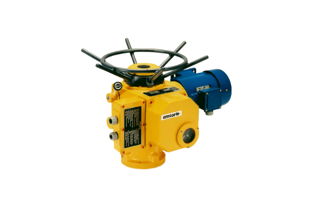
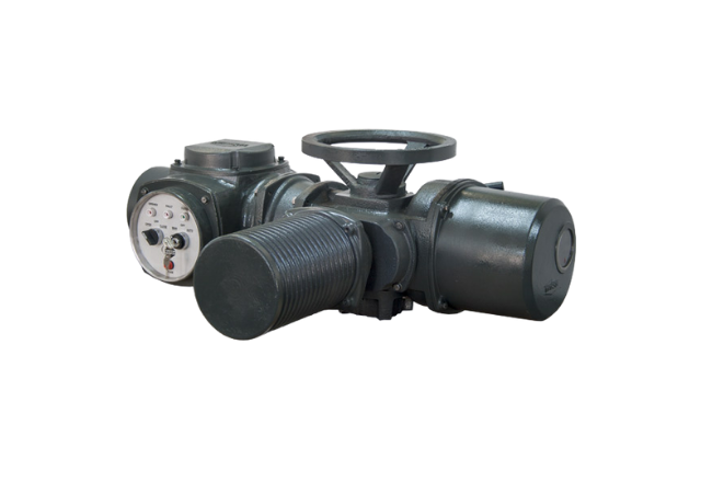
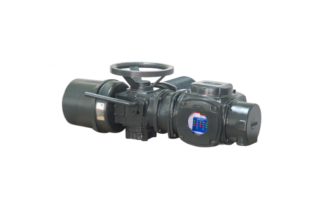
Actuators with Starter
The “Emtork” Electric Actuators are electromechanical units used for operating the final control elements like valves or dampers to control the flow of fluids flowing thru the pipes or ducts. The specific advantages of using these units are :
- Ease of operation.
- Remote control facility.
- Proportional action of final control element in close loop system.
- Attaining & holding the desired preset position of the valve/damper.
- Various indications & alarms are available on the remote control panel & also on the unit.
- Emergency manual operation possible in case of power failure.
- Works on most convenient & easily available source of energy i.e. electricity.
- Models available to cover wide range of valves & dampers.
- Units with Integral starter will save cost of cables.
- Units with Electronic controller will facilitate field programming.
- The Basic design of the Emtork Actuator consists of an electric motor, reduction gear unit and control compartment.
- Various models have been developed to suit operating torque, speed, process parameters, area of operation etc.
- Additional supplementary spur and worm gear boxes are offered to get higher operating torques and quarter turn motion.
- Linear motion actuators have been developed to impart the required thrust to operate globe valves.
- The models are available for on / off and regulating duly and also for hazardous area application.
Modes | Types | Models |
| On/Off-Isolating Modulating/ Regulating Safe Area Flame/Explosion Proof | Multiturn | M30, M60, M80, M120, M150, M200, M250, M300, M500, M600, M1000 Also with supplementary spur gear boxes. |
| Quarterturn | QM0, QM1, Rotary actuator with supplementary worm gear boxes Also TM0/WG & TM1/WG | |
| Linear | LM0,LM1 & Rotary actuator with attachment for linear motion |
- Insulation class ‘F’
- Travel limit switches -2 Nos (1NO + 1 NC)
- Torque limit switches -2 Nos(l NO + 1 NC)
- Continuous type local position indicator
- Handwheel with clutch mechanism
- Protection class IP 65
- Various types of output couplings viz A/B/C/D/E as per DIN 3210
- Hammer-blow effect
- Electric motor- TESC,3ph,S2 OR S4 Duty
- Better class of insulation for motor
- Travel limit switches 2 NO+2 NC in place of 1 NO+1 NC-2 Nos
- Torque limit switch 2 NO + 2 NC in place of 1NO+1NC-2Nos
- Additional Travel limit switches (1 NO + 1 NC) – 4Nos(Extra) –or (2 No. + 2 NC – 2 Nos. extra)
- Feed back potentiometer
- Remote position indicators-Analogue / Digital / Bar graph
- Space heater
- Electromagnetic, Electronic brake for the motor
- Protection class IP67/IP68
- Various types of local & remote panels
- Foot mounting brackets
- Set of linkages
- Tailor made accessories to suit customer’s specific requirements
- Thermostats in motor winding
- Field / Panel mounted source to Convert 220VACto 24 VDC required for transmitter
- Supplementary Spur Worm gear boxes
- Attachment for linear motion
- Retrofitting
Electric motor TEFC, 3ph, S-1 Duty
Emtork actuators are equipped with three phase, squirrel cage induction motor having high starting torque. These motors comply with IS-325 specifications.
| Supply condition | 415 VAC, 3ph / 380VAC,3ph / 2 20 VAC,1ph |
| Enclosure | TEFC/ TESC |
| Class of insulation | std.’F’ |
| Class of protection | IP55 / 65/67/68 |
| Duty | S1 / S2 / S4 |
| Ambient temp | 50° c |
Travel limit switches:
These switches are provided to cut off the actuator supply at the end of the preset travel in either direction. These switches are operated by cams which can be reset at site. Additional travel switches can be provided to get feed back of various valve positions
These switches are provided to cut off the actuator the torque developed in the system is more than the desired preset value, in either direction. Torque switch in closing direction can also be set to achieve leak-proof / tight shut off of the valve.
A continuous type mechanical local position indicator is provided on the actuator to show the actual mechanical position of the final control element.
Emtork actuator is provided with a handwheel for emergency manual operation. The selector fork lever when put on to ‘hand-position’, disconnects the motor drive and connects to hand wheel drive so that desired operation can be done by hand wheel. When the motor is switched on, the hand wheel connection gets disengaged automatically and the operation is carried out by electric power.
The emtork actuators are supplied with IP65/IP67/IP68 class of protection as per IS-4691 & IS-2147 duly certified by concerned authorities. The ingrace of dust and water is prevented to protect the inside mechanism.
The basic rotary actuators are supplied A,B,C,D,E as per DIN 3210.
An inbuilt feature of the ‘emtork’ actuator and is achieved thru “lost motion principle” and by using higher starting torque motor.
A feed back signal, in terms of change in resistance or current proportional to the valve position, is available thru potentiometer or transmitter. A non- contact LVDT type transmitter can also be provided.
The signal coming from potentiometer is converted thru stabilized power source and read by analogue/digital on remote panel
An anti-condensation heater can be provided in the switching compartment while using the actuator in humid/damp environment.
Electromagnetic or electronic brake can be provided for the motor to stop the actuator instantly
Various types of control panels can be provided for local, remote and combined local plus remote operations of the actuator.
Panel or field mounted electronic positioner can be supplied which can accept a control command of 4-20mA and position the final control element accordingly, 4-20 mA feed back signal is also available from the positioner.
A reversing starter consisting of push buttons, indicating lamps, contactors, O/L relay etc. can be supplied as an integral part of the actuator. This will save a major cost of cabling. A parallel operation & monitoring from remote station is also possible. A field mounted valve positioner unit can also be supplied in the integral panel.
Field programming thru electronic logic is possible by this integral panel. In addition to the electrical hardware various PCBs are provided to select the parameters such as inching / noninching operation, closing by torque switch etc. Parallel functions from remote station are also possible.
An actuator mounted transmitter can be supplied which will indicate that the actuator is in running condition, thru a blinking lamp on control panel.
These items can be supplied to suit various site conditions so that the final control element can be operated from a distant location.
These are embedded in the motor winding so as to protect the motor from burning due to overheating of motor winding.
A field / panel mounted source can be supplied for converting 220 VAC to 12/24/36 VDC, supply which is normally required to energize a two wire transmitter.
To increase the output torque of rotary actuators various types of spur gear boxes can be supplied. These gear boxes have variety of reduction ratios & output couplings viz A/B/C/D/E as per DIN 3210.
Worm gear boxes can be supplied to convert the output motion of rotary actuator in to quarter-turn movement to suit the operations of butterfly, ball & plug valves. Various models are available with different reduction ratios. Out put coupling for these models will be normally ‘E’ for direct mounting & ‘D’ for mounting thru brackets & linkages.
To convert rotary motion into linear to suit globe valves, a linear attachment is provided for the actuator. Various thrust values are available to suit the applications.
To convert the existing manually operated valves into “motor-operated”, retrofitting services are offered; which includes, site study, selection of equipment, spot measurement, designing & manufacturing mounting brackets, couplers, cabling etc. and installation and commissioning of equipment on turnkey basis. This will also cover the services of compating / synchronizing the system with control parameters of other instruments.
| Model | Output Data | Motor Data | ||||||||
|---|---|---|---|---|---|---|---|---|---|---|
| Output Speed RPM (Aprox.) | Output Torque Nm | Actuator Self Locking | Rated Power HP | No. of Poles | Rated Current AMP (Aprox.) | Power Factor FL | Effi. % (FL) | Mounting Base As per IS 9334 | ||
| Rated | Adj Range | |||||||||
| M30 | 10,15,20 30,40 65,90 120,150 | 30 | 10-30 | Yes Yes Yes No | 0.16 0.25 0.35 0.50 | 4 2 2 2 | 0.42 0.57 0.71 1.00 | 0.75 0.76 0.79 0.78 | 53 58 62 67 | F10 |
| M60 | 10,15,20 30,40 65,90 120,150 | 60 | 20-60 | Yes Yes Yes No | 0.16 0.25 0.50 1.00 | 4 2 2 2 | 0.42 0.57 1.00 1.70 | 0.75 0.76 0.78 0.82 | 53 58 67 75 | F10 |
| M80 (M0) | 1O to 70 80 to 140 190 to 365 | 80 | 25-80 | Yes Yes No | 1.00 3.00 3.00 | 4 2 2 | 1.80 4.55 4.55 | 0.78 0.83 0.83 | 76 81 81 | F10 |
| M120 | 10,15,20 30,40 65,90 120,150 | 120 | 40-120 | Yes Yes Yes No | 0.25 0.50 1.00 1.50 | 4 2 2 2 | 0.58 1.00 1.70 2.40 | 0.75 0,78 0.82 0.82 | 58 67 75 79 | F10 |
| M150 | 10,15,20 30,40 65,90 120,155 | 150 | 50-150 | Yes Yes Yes No | 0.35 0.75 1.50 2.00 | 4 2 2 2 | 0.77 1.33 2.40 3.10 | 0.74 0.79 0,82 0.86 | 61 73 79 78 | F10 |
| M200 (M1) | 10 to30 40 to 60 80 to 120 | 200 | 60-200 | Yes No No | 1.00 2.00 3.00 | 4 4 2 | 1.80 3.30 4.55 | 0.78 0.80 0.83 | 76 78 81 | F14 |
| M250 | 10,15,20 30,40 65,90 120,150 | 250 | 80-250 | Yes Yes Yes No | 0.50 1.00 2.00 3.00 | 4 2 2 2 | 1.04 1.70 3.10 4.55 | 0.72 0.82 0.86 0.83 | 69 75 78 81 | F14 |
| M300 | 10,15,20 30,40 65,90 120,150 | 300 | 100-300 | Yes Yes Yes No | 0.75 1.50 3.00 5.00 | 4 2 2 2 | 1.40 2.40 4.55 7.20 | 0.78 0.82 0.83 0.87 | 72 79 81 82 | F14 |
| M500 | 10,15,20 30,40 65,90 120,150 | 500 | 160-500 | Yes Yes Yes No | 1.00 2.00 5.00 7.50 | 4 2 2 2 | 1.80 3.10 7.20 10.20 | 0.78 0.86 0.87 0.89 | 76 78 82 84 | F14 |
| M600 | 10,15,20 30,40 65,90 120,150 | 600 | 200-600 | Yes Yes Yes No | 1.50 3.00 5.00 7.50 | 4 2 2 2 | 2.50 4.55 7.20 10.20 | 0.81 0.83 0.87 0.89 | 76 81 82 84 | F14 |
| M1000 | 10,15,20, 30,40,60, 80, 120 | 1000 | 300-1000 | Yes Yes Yes No | 1.5 3 5 10 | 6 4 2 2 | 2.9 4.6 7.2 14 | 0.69 0.82 0.87 0.88 | 76 81 82 85 | F16 |
- At higher speeds the rated output torque may get reduced slightly.
- For regulating Duty models the output speed of the actuator should be restricted up-to 40RPM to avoid inertia problems.
- Additional details for regulating duty models will be available on request.